|
|
|
|
|
|
Classic Bikes
Custom Bikes
Individual
Racing Bikes AJP
AJS
Aprilia
Ariel
Avinton / Wakan
Bajaj
Benelli
Beta
Bimota
BMW
Brough Superior
BRP Cam-Am
BSA
Buell / EBR
Bultaco
Cagiva
Campagna
CCM
CF Moto
Combat Motors
Derbi
Deus
Ducati
Excelsior
GASGAS
Ghezzi Brian
Gilera
GIMA
Harley Davidson
Hero
Highland
Honda
Horex
Husaberg
Husqvarna
Hyosung
Indian
Jawa
Kawasaki
KTM
KYMCO
Laverda
Lazareth
Magni
Maico
Mash
Matchless
Mondial
Moto Guzzi
Moto Morini
MV Agusta
MZ / MuZ
NCR
Norton
NSU
Paton
Peugeot
Piaggio
Revival Cycles
Roland Sands
Royal Enfield
Sachs
Sherco
Sunbeam
Suzuki
SWM
SYM
Triumph
TVS
Ural
Velocette
Vespa
Victory
Vincent
VOR
Voxan
Vyrus
Walt Siegl
Walz
Wrenchmonkees
Wunderlich
XTR / Radical
Yamaha
Zero
Video
Technical
Complete Manufacturer List |
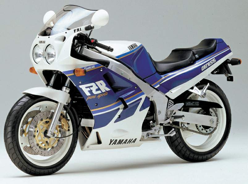
Yamaha FZR 750R Genesis
Source Cycle Magazine of 1987 With the introduction of the 1987 models, though, particularly the new FZR Yamahas, we're beginning to see two elemental yet heretofore disparate motorcycling structures—chassis and engines—come together in a technical harmony and balance the sport hasn't seen since the Norton featherbed. Not that Yamaha has a corner on the technological market by any means. Honda with its CBR fours, however, appears to be exploring the aerodynamic route to speed while the bikes make do with steel perimeter chassis. Suzuki's and Kawasaki's aluminum street chassis don't yet reflect the current spar-design thinking which is winning on the Grand Prix circuit, and while the oil-cooled Suzuki engines push the light bikes to respectable speeds, the engines themselves aren't powerhouses. No, out of the few 1987 models the Japanese let the press peek at, our vote for the most homogenized mixture of current-think parts goes to Yamaha. A collection of high-tech bits does not guarantee a great bike, yet this assemblage seems to represent the future, now. What are we looking at? Clearly, two performance innovations combined: Yamaha's use of a five-valve-per-cylinder head on the FZR bikes, set for the first time in the company's race-bred Deltabox aluminum chassis. Because the sum of these innovations has such import, it's helpful to evaluate the parts separately, winnowing the misconceptions from the truth. First, the cylinder head Yamaha developed its novel five-valve technology for specific gains. First on the list was a compact, nearly flat combustion chamber of minimum surface area. In a two-valve design, adequate valve area comes only by tilting the valves away from each other and making the head somewhat hemispherical, but with five valves the poppets can set into an almost flat chamber. The Yamaha's head is only slightly domed, its piston slightly concave. The resulting lens-shaped chamber concentrates the charge tightly around the central spark plug, and this means most of the charge is quickly inflamed shortly after the spark. The resulting short total combustion time cuts energy loss through heat to the cooler metal of the piston and head, and that saved energy is applied to the job of pushing the pistons down. Being nearly flat, both piston and head offer minimum surface area, and this further cuts combustion heat loss, again translated into power gains. Detonation—engine knock—sets the upper limit on compression ratio, but the five-valve's rapid combustion can consume the charge before detonation has time to occur, permitting an unusually high compression ratio of 11.2:1 (Honda's VFR750 is good for 10.5:1, Suzuki's GSX-R750 10.6:1). This not only gives the Yamaha 750 and 1000 more punch across the powerband, it also increases fuel economy.
The paired exhausts and trebled intakes bring more advantages. To explain one, we'll use a two-stroke analogy. Imagine two cylinder-wall ports, one wide and short, another narrow and tall. Both 'have the same area when fully open. Clearly, as the piston falls, the wide port will expose flow area faster—because the narrow port is taller, it will take longer to open fully. Yet when both are fully open, they have identical area. Now for the four-stroke equivalent. Imagine two engines, one built with a single, large intake valve, the other with three much smaller intakes of identical total head area to that of the large one. Imagine that we equip these engines with cams that accelerate the valves at identical rates. Which design will expose flow area more quickly? In analogy with the two-stroke case, our flow area will be the "width" of the port multiplied by the distance it is opened. For the four-stroke, the width equates to the perimeter of the intake valve or valves. The height is the valve lift—the same for both engines because the valves are opening at the same rate. Consider specific cases; the distance around a single 37mm intake valve is pi times 37, or about 116mm. Three valves of the same total head area would be 21.4mm diameter each, and the distance around all three will be pi times three, times 21.4, or 202mm. Our three-intake-valve design exposes flow area 1.74 times faster (202 ± 116) than a single-valve design. Work the figures for the twin intakes of a four-valve setup and you find the five-valve Yamaha concept has a 22 percent advantage in rate of area exposure. Here's a third benefit: Rapid opening gets the valve(s) out of the way of the flow quickly, keeping the loss-producing restriction between valve and seat to a minimum. Unfortunately, getting the valve open fast means serious acceleration levels—up to 3000 times the force of gravity in some racing engines. High valve opening and closing rates bring problems—like seat hammering, cam and tappet scuffing, seat recession or loosening, or outright valve breakage. The standard ways of limiting valve acceleration are to reduce the lift and/or extend duration. Both have drawbacks: cutting the lift cuts the flow, and extending the duration invites reverse flow from the cylinder to the intake pipe; either cuts power. The Manx Norton road racer had a radical 340-degree intake duration, thought by many to be its key to high performance, but much of that impressive timing existed because the designer couldn't get those big, heavy valves up off their seats in anything less without breaking them. The Manx could actually have made more power, and over a wider range, had it been able to run less intake timing. These compromises were cut perilously close in many cases; the great 1960s MV road racers would toss their valves if overrevved by only 300 rpm!
Ideally, as the piston nears the bottom of its intake stroke at high revs, the fuel/air charge is rushing towards the valve at something over 300 feet per second, and this velocity doesn't disappear just because the piston stops at BDC and reverses direction. It's desirable to keep the intake(s) open past BDC long enough to let this fortune in intake kinetic energy—a kind of free supercharging—spend itself against the rising piston, forcing in extra mixture to make extra power. At the instant that intake flow piles to a stop against the rising pressure in the cylinder, the intake(s) should snap shut, trapping these goodies. But as we have observed, valves and springs can only take so much acceleration, and hence two-valve designs suffer under a severe compromise between what is best for airflow and power and what is possible mechanically. Again, the answer is smaller valves and more of them. Scale a part down in dimensions and it loses weight faster than it loses strength—weight is proportional to roughly the cube of the linear dimension, while the strength is related to a lesser power. This means small valves can stand higher acceleration rates than can large ones. Consequently, not only do many small valves expose perimeter area faster than a single one of equal total area, but they can also be opened faster to redouble the effect. What Yamaha gets in return for its extra parts is an unusually wide and strong powerband. A two-valve or four-valve engine could be made to give as much peak power, or as much low-end and mid-range, but not both. The Yamaha makes its numbers with grace, not with extremes of materials or design. Next comes the matter of 'valve springs. From your place on a tall stool in an air-conditioned drafting room, logic tells you that two revolutions of the crank equals one valve-spring fatigue cycle. From the hot dyno cell or race track, the springs see things differently: at high crank speeds the rapid acceleration imparted by the cam lobe approximates a hammer blow. This can make the coils of valve springs "ring" or vibrate end-to-end. This ringing vibration may have a characteristic frequency of hundreds of cycles per second, so it can, if excited at high speed, add up fatigue cycles so fast that springs break prematurely. This spring surge can also cause irregular actions at the valve—float, bounce, etc.—that deteriorate other parts as well. Designers like "soft" rate springs—those with little difference between their seat pressure and their open pressure. Why? Too much spring pressure can overload the oil film between cam and tappet, leading to scuffing. Unfortunately, such springs also tend to have low natural frequencies. Standard texts on valve-gear design suggest the spring frequency should be at least eleven times the camshaft speed, but it is difficult to provide for a large single spring or spring pack sufficient to close a single large intake valve in a high-rpm engine. Such high-revvers need high-rate springs with very few coils, operating at extreme stress levels, manufactured with special processing and many inspections. Expensive, and difficult to make. On the other hand, three tiny valves eliminate most spring problems. Tiny springs are now all you need to handle the job, and such small springs provide high natural frequencies without high-tech manufacturing and expense. The single springs Yamaha uses are dualrate—the coils wound with two pitches, a fine and a coarse. With the valve closed, all the coils are in action; as the spring compresses during valve lift, the fine-pitch section coil-binds, leaving only the coarse coils in action. This in effect gives the spring two natural frequencies instead of one: a lower frequency when the valve is closed, a higher one when it is open. This "confuses" spring surge by favoring first one and then the other frequency, and tending to suppress others in between. Using one large intake, the designer must save all the weight he possibly can by making the valve's stem skinny and short, and thinning down the head. Such compromise valves usually employ stems whose diameter is only 18 percent of the valve-head diameter. Such valves, while light, affect both durability and performance. They cramp the intake port into a hunched-over position, huddled close under the valve spring seat and making a sudden 90-degree turn to enter the cylinder. This forces designers to use a short, unsupportive valve guide that soon wears out, leaks, and forces the valve to leak. Second, the sudden 90-degree turn flings most of the airflow to the outside of the bend, so it enters the cylinder through only half of the valve's circumference. These losses show up on a torque curve, making foothills out of what might have been mountains. Yamaha's three small intake valves can afford stem diameters a full 25 percent of their head diameter, and their length is more than four times their head diameter—like the best racing designs. This allows excellent, long-lasting support from an adequate valve guide that doesn't intrude into the port, and also provides room for a nearly straight downdraft intake of excellent airflow qualities. Yamaha chose to operate all these valves in racing fashion, using one cam lobe and inverted-bucket-type tappet per valve. Why not cut manufacturing costs and ease maintenance by incorporating some form of forked rocker arms, with clearance adjustment by screws and lock-nuts? What was gained in valve-acceleration tolerance by using small poppets could easily be thrown away by introducing a flexible element into the system—a rocker arm loaded in bending. A rocker arm is effectively a high-rate spring, inserted between cam lobe and valve. When the lobe accelerates the tappet, the spring first winds up, and only then begins to lift the valve. When the cam contour calls for the valve to slow for peak lift and then reverse, the spring unwinds, then continues to oscillate for the rest of the valve event. If the rocker-arm "spring" is again unwinding as the valve approaches its seat, the valve may hit the seat with not only the seating velocity built into the cam contour but also with the extra velocity resulting from rocker-arm unwinding. If the rpm is up, and the designed-in seating velocity is already on the high side, the result will be seat hammering, recession, or loosening. With the rocker arm oscillating like this, it too can pile up fatigue cycles like a surging valve spring until it breaks as well. To go with their high-rpm, rockerless valve gear, Yamaha chose the most reliable method of valve clearance adjustment—selective-fit lash caps on the valve stem ends. Unlike clearance discs (shims) set into recesses on the tops of the bucket tappets, these cannot come adrift during valve float, free to wreck the top end. Adjusting clearance with this bulletproof system does require removing the cams, but Yamaha has used hardened cam lobes to extend the service interval. And what about gross flow? Do three valves flow more air than one or two? Years ago, Harry Weslake, the famous English airflow pioneer, believed he had proven one valve was best—it minimized wall-friction losses. True, but that small gain ignored the huge gains that would soon come from the use of multiple, long-stemmed valves and gently curved ports. It also ignored the greatly increased safe rev limit and durability of multi-valve designs; either of these advantages by itself is enough to make nonsense of any putative extra flow through a single valve. Is there any limit to the process of valve multiplication? Yamaha has tried as many as seven valves—four intakes and three exhausts—in larger-bore engines. Five valves seem to work best in motorcycle sizes; more tend not to leave enough head material between seats and spark-plug holes. On the other hand, the old process of forming all the valve seats and the spark-plug threads as a single austentic iron insert set into the aluminum head might offer a way around even that limitation. The iron insert would have another advantage as well; small, big-bore engines have a lot of combustion chamber surface area in relation to volume, and that means rapid heat loss. Compared to aluminum, iron is an insulator that has proven its ability to keep the heat where it belongs—in the combustion gases. So five-valve engines are the ticket in—we knew that last year, and they haven't changed much for 1987. Show us something new, you say? Right this way. While you've seen aluminum chassis on the street before, you've never seen one so close to the track as this one. Conventional motorcycle chassis have almost always been made from tubes—bolted, brazed, or welded together. If any tubing is made smaller and of heavier wall thickness, so the weight per foot remains constant, the bending and torsional stiffness of the tubing drops, reaching the lowest limit as the tube becomes a solid bar. Reverse the process and the tube becomes stiffer roughly in proportion to the square of the tube diameter until at the other extreme the likelihood of the now very thin wall crumpling under load becomes greater than the possibility of actual rupture or tearing of the material. Designers seek- ing a high stiffness-to-weight ratio make their structures with the largest possible diameter and the thinnest possible wall. A single-tube chassis represents the conceptual ultimate in bending and torsional resistance; many experimental frames have been built this way. Ken Sprayson, a noted English frame specialist, built steel single-beam chassis in the 1950s. In 1969 the Spanish OSSA firm fielded a welded-sheet aluminum 250 road-racing chassis. Harry Hunt constructed one of riveted aluminum sheet two years later. The erratic innovator Eric Offenstadt ran a welded aluminum monocoque 750 at Daytona in 1972. These experiments apparently showed only that aluminum could not long survive the vibration of motorcycle service. We now know correct design procedures can produce aluminum structures of any desired lifetime, even in a motorcycle chassis, but there is a compromise between weight and life. High-frequency engine vibration is deadly to thin aluminum, yet in 1979 Yamaha pioneered conventional multi-tube designs in a welded-aluminum chassis with wall thicknesses of two to three millimeters. The light metal allowed both the wall thickness and diameter to increase with no weight penalty. Soon they were both stiffer and lighter than steel designs, and durable enough to last more than one race. How do you stiffen an existing twin-loop frame? The goals are clear: the steering head shouldn't flex and should resist braking forces, the frame must be stiff enough torsionally to prevent the wheels from straying from their common plane, and untriangulated bays should be braced with diagonals. The best way to do this is to deepen the top frame rails to better resist bending and torsion, and to provide equally deep cross-members to make the two work together. Make the load path direct between steering head and rear fork pivot. Do this and watch the top frame rails grow and the lower loops shrink into mere engine-hangers. The opening between the top rails remains to provide clearance for engine upper structure, or for service access. The 1982 racing season was a turning point for Yamaha. The company had mastered the multi-tube aluminum chassis and began working towards something else in very much the way described above. That something else was the OW61, a motorcycle not in itself successful, but a necessary step towards the future. If you looked at that chassis with 1982 hindsight it was just a twin-loop design with its engine hanging from already-shrinking lower frame members. The engine, too, was significant, its two cylinder pairs set close to 90 degrees, a configuration that cancels major vibratory forces. The engine was supported in rubber mounts since the chassis designer had finally decided to make the chassis stiff enough to do its job unassisted and let the engine provide only power. The concept of a load-bearing engine is attractive, but such a system fatigues an aluminum frame's welds.
The following year the upper rails grew again, the lower members shrinking correspondingly. Yamaha repeated the process each succeeding year: the current Yamaha YZR500 road racer's chassis is a delta-shaped twin boxbeam, made as deep as the steering head and as wide as it must be to clear the engine. It extends almost straight from head to swing-arm pivot, and is made largely from special weldable aluminum sheet about two millimeters thick. Almost without exception, previous designs have carried steering-head bearings in the ends of a piece of tubing—the steering head proper—and have joined the rest of the structure not to the bearing area, but to the head tube, relatively far from the bearings. This sacrifices strength by cantilevering the bearings out in space above and below the points at which chassis loads are fed in. Yamaha put top and bottom bearings into pieces of plate which extend rearward into the box structure, directly carrying head-bearing loads into the frame. A tube separates the bearing pair, but it is no longer loaded in bending. At the rear, plates at the side pick up the rear fork pivot pin and the footpeg carriers. Between the steering head and swing-arm pivot, the twin beams are gracefully shaped, cross-members blended into them in organic-looking fashion. Although the original OW61 used extruded frame tubes, Yamaha's present racing chassis are fabricated from machined shapes and from special-purpose pressings in sheet aluminum. Why do they last when frames before them cracked? Using the longest possible welds cuts down the load per inch of bead. In the Deltabox, the welds have the same dimensions as the frame itself, and because the frame is largely continuous pressings, there is a bare minimum of welds in the first place. The resulting structure probably has about five times the torsional and bending stiffness of previous multi-tube designs. In the new FZR Yamahas, we now have a Deltabox design for the street, significant because this signifies the Deltabox design has passed rigorous vibration, drop, and longevity testing. As in the competitors' aluminum chassis, Yamaha uses high-quality castings for the steering-head and swing-arm structures, a cost-cutting move. Castings have poor fatigue properties as compared with wrought materials (rolled or extruded mill forms) because traditionally most castings are full of voids or impurities, both of which invite crack growth under stress cycling. On the other hand, castings lend themselves to high-volume production where machining from solid stock does not. There is an answer, though. Traditional die-casting fills the die by gravity flow, and dissolved gases in the metal pass out of solution during solidification to form voids. Vacuum casting fills the die by drawing the metal up from below: as the liquid emerges into the mold, the low pressure there causes evolution of the gases in much the same manner as uncapping a bottle of soda. The result is a casting with greatly improved fatigue properties. Another approach is Hot Isostatic Pressing (HIP), which submerges castings in a hot, high-pressure (15,00030,000 psi) bath, in effect forging the part from all directions, closing the voids, and therefore reducing the population of crack nucleation sites. The formed-aluminum sections of a Deltabox chassis, pressed in the same fashion as auto body parts, already lend themselves well to quantity production with no sacrifice in strength. Welding aluminum is tricky. Any welding process is really a continuous casting in which the molten weld puddle freezes behind the moving torch arc. Just as the freezing of sea water yields fresh-water ice and a slush of concentrated salt water, the freezing of the weld puddle has some tendency to produce a weld area of purified aluminum with a zone of concentrated impurities and alloying elements down its centerline. Aluminum expands far faster than steel; after welding its cooling contractions may tear the bead apart, particularly in that sensitive, impurity-rich centerline zone. Welds made with "high restraint"—on parts jigged so firmly they cannot move easily during cooling—are especially subject to cracking in this fashion. Taking care in the design not only of the chassis but of how its welds are sequenced can make the difference between cracking and not cracking. Yamaha uses robots to weld their aluminum frames, and began using robot welders in 1974. The trend in robotics in the U.S. is toward many-jointed arms that mimic human function; in Japan robots now tend to be specialized for particular jobs. Yamaha builds its own robots for about half the cost of commercially available machines, and in a typical operation, several machines work with one or more human "stagers." The stager picks up frame elements and locates them accurately into a fixture on .a rotary table—such fixturing is very difficult for robots, but easy for humans. The table indexes 180 degrees, carrying the fixtured part into the operating envelope of the robots. A glare curtain sweeps across, protecting the worker's eyes from the ultraviolet light as the welding begins, often performed by more than one robot simultaneously. The worker removes the just-completed part and fixtures another. He may also complete welds in areas difficult for the machines to reach. Why robots? Can you repeatedly place an arc source to within 0.004 inch anywhere in space, eight hours a day, Monday-morning hangover or no? What can Yamaha—or any other manufacturer for that matter—do for an encore? The latest FZRs still look a step behind in the aerodynamic fight: maybe slicker bodywork for '88. Or how about a reliable, responsive fuel-injection system? And aluminum isn't the only stuff to make frames from: a carbon-fiber chassis? A ceramic cylinder block? When will center-hub steering come of two-wheeled age? Yamaha's five-valve engines and Deltabox chassis are but a momentary stay against the unending rush of technology, but together they represent a canny balance between performance and handling, between technology and rider ability. The featherbed Nortons did the same, and we remember and revere such machines even today. Will these new Yamahas be worthy of such immortality? We'll all soon know Source Cycle Magazine |
|
|
Any corrections or more information on these motorcycles will be kindly appreciated. |